Home Lab – Network Setup – Part 1.

This is the first article in a technical blog series focused on network security and building a proper home lab environment. Throughout this series, I’ll show you how to set up secure and well-structured systems where you can safely test, deploy, and experiment with various technologies.
The network will be segmented and VLAN routing will be implemented using MikroTik hardware, allowing the home network to be separated from the workshop environment, which will be used for testing, demonstrations, and work-related activities.
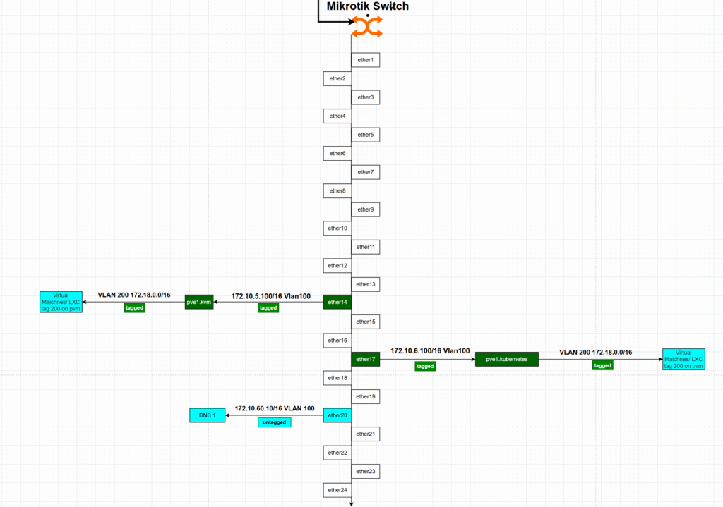
In the diagram below, I present the planned network topology with VLAN separation. Each VLAN has a specific purpose, and firewall rules are configured to isolate the home network from the others. For selected hosts within the secure VLAN, custom forwarding rules will allow controlled access to certain IP addresses within internal VLAN segments.
*The commands shown in blue can be entered using the MikroTik terminal.
However, the same steps can also be performed through the Web GUI interface.
** To build the diagrams I have used draw.io tool.


Step 1: Define Bridge and Assign Interfaces
The first step is to create a bridge interface that will serve as the backbone for VLAN management. MikroTik supports bridging physical interfaces, making it a flexible solution for VLAN setups.
➤ Create a Bridge with VLAN Filtering Enabled
Go to Interfaces > Bridge and add a new bridge. Enable VLAN filtering and keep default settings.
/interface bridge
add name=PrivateNetwork vlan-filtering=yes
Step 2: Add Physical Interfaces to the Bridge
Now add the physical interfaces you plan to use to the bridge. These are the ports that will carry VLAN-tagged (trunk) or untagged (access) traffic.
/interface bridge port
add bridge=PrivateNetwork interface=ether1
add bridge=PrivateNetwork interface=ether2
add bridge=PrivateNetwork interface=ether3
Adjust ether1, ether2, etc., depending on your setup.
Step 3: Define VLANs in the Bridge VLAN Section
Now define which VLANs will be allowed and how the tagging works per port. This is done under Bridge > VLAN.
/interface PrivateNetwork
add bridge=PrivateNEtwork vlan-ids=100 tagged=bridge-vlan,ether1 untagged=ether2
add bridge=PrivateNetwork vlan-ids=200 tagged=bridge-vlan,ether1 untagged=ether3
add bridge=PrivateNetwork vlan-ids=300 tagged=bridge-vlan,ether1
VLAN Descriptions:
- VLAN 100 – Blue: Management VLAN
- VLAN 200 – Light Blue: Network VLAN for home communication
- VLAN 300 – Green: DMZ/test VLAN
- Tagged (Trunk) Traffic: Green
- Untagged (Access) Traffic: Light Blue
In this example:
ether1is the trunk port (tagged) carrying all VLANs.ether2is an access port for VLAN 100 (Management).ether3is an access port for VLAN 200 (Home Network).- VLAN 300 is only tagged and used via trunk.
Step 4: Assign IP Addresses to VLAN Interfaces
Now that VLANs are defined and assigned to the bridge, the next step is to create VLAN interfaces and assign IP addresses. Each VLAN interface will be used to manage routing, DHCP, and firewalling.
➤ Create VLAN Interfaces
/interface vlan
add name=vlan100-mgt vlan-id=100 interface=PrivateNetwork
add name=vlan200-network vlan-id=200 interface=PrivateNetwork
add name=vlan300-secure vlan-id=300 interface=PrivateNetwork
➤ Assign IP Addresses to Interfaces
/ip address
add address=172.10.0.1/16 interface=vlan100-mgt comment="Management Network"
add address=172.18.0.1/16 interface=vlan200-network comment="Network VLAN"
add address=172.19.0.1/16 interface=vlan300-secure comment="Secure VLAN"
add address=192.168.179.X/24 interface=ether1 comment="Upstream WAN / ISP"
Description of VLAN Interfaces
| Interface | IP Address | Subnet | Description |
|---|---|---|---|
vlan100-mgt | 172.10.0.1/16 | 172.10.0.0 | Management VLAN (Blue) |
vlan200-network | 172.18.0.1/16 | 172.18.0.0 | Home Network VLAN (Light Blue) |
vlan300-secure | 172.19.0.1/16 | 172.19.0.0 | Secure VLAN (DMZ/Test – Green) |
ether1 | 192.168.179.X/24 | 192.168.179.0 | WAN / Upstream ISP |
Step 5: Configure DHCP Servers for Each VLAN
Each VLAN in your MikroTik setup can have its own DHCP server and pool. This makes it easier to manage devices per segment and improves isolation and auditing.
DHCP Server Overview
| VLAN Interface | DHCP Server Name | Address Pool | Gateway IP | DNS Servers | Lease Time | Add ARP |
|---|---|---|---|---|---|---|
vlan100-mgt | mgt-vlan100 | mgt-pool | 172.10.0.1 | — | 30 mins | yes |
vlan200-network | network-vlan200 | network-pool | 172.18.0.1 | 8.8.8.8, 1.1.1.1 | 30 mins | no |
vlan300-secure | dmz-vlan300 | dmz-pool | 172.19.0.1 | — | 30 mins | no |
Create Address Pools
/ip pool
add name=mgt-pool ranges=172.10.0.100-172.10.0.200
add name=network-pool ranges=172.18.0.100-172.18.0.200
add name=dmz-pool ranges=172.19.0.100-172.19.0.150
add name=default-dhcp ranges=192.168.88.10-192.168.88.254
Add DHCP Servers
/ip dhcp-serveradd name=mgt-vlan100 interface=vlan100-mgt address-pool=mgt-pool lease-time=00:30:00 add-arp=yes
add name=network-vlan200 interface=vlan200-network address-pool=network-pool lease-time=00:30:00
add name=dmz-vlan300 interface=vlan300-secure address-pool=dmz-pool lease-time=00:30:00
add name=PrivateDHCP interface=PrivateNetwork address-pool=PrivateDHCPPool lease-time=00:30:00
add name=defconf interface=bridge address-pool=default-dhcp lease-time=00:10:00
Set DHCP Networks
/ip dhcp-server network
add address=172.10.0.0/16 gateway=172.10.0.1 comment="mgt"
add address=172.17.0.0/24 gateway=172.17.0.1 dns-server=8.8.8.8,1.1.1.1 comment="HomeLabNetwork"
add address=172.18.0.0/16 gateway=172.18.0.1 dns-server=8.8.8.8,1.1.1.1 comment="network"
add address=172.19.0.0/16 gateway=172.19.0.1 comment="DMZ"
add address=192.168.88.0/24 gateway=192.168.88.1 dns-server=192.168.88.1 comment=
Step 6: Configure Firewall and NAT Rules
In this step, we’ll apply firewall filtering and NAT rules to:
- Ensure inter-VLAN isolation
- Block unwanted access to the upstream network (
192.168.179.0/24) - Allow selective traffic (e.g., from admin subnet)
- Masquerade outbound traffic
Block Unwanted Traffic
Block All Access to 192.168.179.0/24 from VLANs
/ip firewall filter
add chain=forward action=drop dst-address=192.168.179.0/24 comment="Block all to 192.168.179.0/24"
Block VLAN 172.18.0.0/16 (Network) from accessing 172.10.0.0/16 (Management)
/ip firewall filter
add chain=input action=drop src-address=172.18.0.0/16 dst-address=172.10.0.0/16 comment="Block network VLAN to management (input)"
add chain=forward action=drop src-address=172.18.0.0/16 dst-address=172.10.0.0/16 comment="Block network VLAN to management (forward)"
Allow Essential Local Traffic
Allow Admin Subnet (172.10.0.0/24) Access to Router for Management
/ip firewall filter
add chain=input action=accept src-address=172.10.0.0/24 dst-address=172.10.0.7 protocol=tcp dst-port=22,80,8291 comment="Allow admin subnet management"
add chain=input action=accept src-address=172.10.0.0/24 dst-address=172.10.0.7 protocol=icmp comment="Allow admin subnet ping"
NAT Configuration (Masquerade)
To provide internet access to specific VLANs and isolate local IPs, use masquerade.
Default WAN NAT Masquerade
/ip firewall nat
add chain=srcnat action=masquerade out-interface-list=WAN comment="defconf: masquerade"
Masquerade for HomeLab VLANs
/ip firewall nat
add chain=srcnat action=masquerade src-address=172.10.0.0/16 out-interface-list=WAN comment="Masquerade Management VLAN"
add chain=srcnat action=masquerade src-address=172.18.0.0/16 out-interface-list=WAN comment="Masquerade Network VLAN"
You can optionally add masquerade for 172.19.0.0/16 (DMZ) if needed.
Allow Specific NAT/Forwarding Use Cases
Allow traffic from 192.168.179.80 to access HomeLab Gateway (172.17.0.0/24)
/ip firewall nat
add chain=srcnat action=masquerade src-address=192.168.179.80 dst-address=172.17.0.0/24 comment="Masquerade HomeLab access from upstream"
Allow HTTP from WAN for Web Interface (if needed)
/ip firewall filter
add chain=input action=accept protocol=tcp dst-port=80 in-interface=ether1 src-address=192.168.179.0/24 comment="Allow HTTP from WAN"
Summary: What This Firewall Setup Does
- Blocks access from insecure or “external” VLANs to the management VLAN
- Prevents routing to the upstream
192.168.179.0/24network except for exceptions (like.80) - Allows local management via Winbox/SSH/Web
- Enables internet access via NAT for selected VLANs
- Provides clean segmentation with the option to expand DMZ/test VLAN rules
Step 7: Controlled Forwarding from the Secure VLAN to Internal Hosts
By default, VLAN 300 (the secure/test network) should be fully isolated from other internal networks (Management, Network, and Private). However, in some scenarios, we may need to allow limited access to specific hosts or services inside other VLANs — for testing, updates, or service integration.
Design Goals
- Default behavior: VLAN 300 (
172.19.0.0/16) cannot access other VLANs. - Exceptions: Only selected destination IPs (e.g., admin tools, Git, web API) are reachable.
- Control: Only certain protocols (e.g., SSH, HTTP/S, ICMP) are allowed.
- Everything else is explicitly blocked.
Step 7.1: Allow Specific Access from VLAN 300
Below are examples of allowed forwarding rules for particular services:
| Destination IP | Service Description | Protocol / Port | VLAN Targeted |
|---|---|---|---|
| 172.10.0.10 | Admin host (SSH access) | TCP 22 | Management VLAN (100) |
| 172.18.0.20 | Internal Web API (testing) | TCP 80, 443 | Network VLAN (200) |
| 172.17.0.50 | Git server (test/dev access) | TCP 22, 9418 | Private VLAN |
| 172.10.0.10 | Ping admin host (ICMP testing) | ICMP | Management VLAN (100) |
/ip firewall filter
add chain=forward action=accept src-address=172.19.0.0/16 dst-address=172.10.0.10 protocol=tcp dst-port=22 comment="Allow SSH to Admin host from Secure VLAN"
add chain=forward action=accept src-address=172.19.0.0/16 dst-address=172.18.0.20 protocol=tcp dst-port=80,443 comment="Allow HTTP(S) to Web API from Secure VLAN"
add chain=forward action=accept src-address=172.19.0.0/16 dst-address=172.17.0.50 protocol=tcp dst-port=22,9418 comment="Allow Git access to Git server"
add chain=forward action=accept src-address=172.19.0.0/16 dst-address=172.10.0.10 protocol=icmp comment="Allow Ping from Secure VLAN to Admin Host"
Step 7.2: Block All Other Inter-VLAN Access from VLAN 300
After defining your allowed exceptions, explicitly block any other attempts from VLAN 300 to reach other internal VLANs:
/ip firewall filter
add chain=forward action=drop src-address=172.19.0.0/16 dst-address=172.10.0.0/16 comment="Block Secure VLAN to Management"
add chain=forward action=drop src-address=172.19.0.0/16 dst-address=172.18.0.0/16 comment="Block Secure VLAN to Network"
add chain=forward action=drop src-address=172.19.0.0/16 dst-address=172.17.0.0/24 comment="Block Secure VLAN to Private"
Optional: Use Address Lists for Easier Management
If you expect to add multiple exceptions over time, consider using an address list to simplify your rule set:
/ip firewall address-list
add list=secure-vlan-allowed address=172.10.0.10
add list=secure-vlan-allowed address=172.18.0.20
add list=secure-vlan-allowed address=172.17.0.50
And allow traffic only to those listed destinations:
/ip firewall filter
add chain=forward action=accept src-address=172.19.0.0/16 dst-address-list=secure-vlan-allowed comment="Allow Secure VLAN to specific hosts"
Then follow up with broader deny rules as above to block anything else.
Summary
This setup ensures that:
- VLAN 300 (Secure) is isolated by default.
- Only explicitly defined hosts and services are reachable.
- You maintain fine-grained control using either direct rules or address lists.
- Future additions (e.g., more allowed services) are easy to manage.
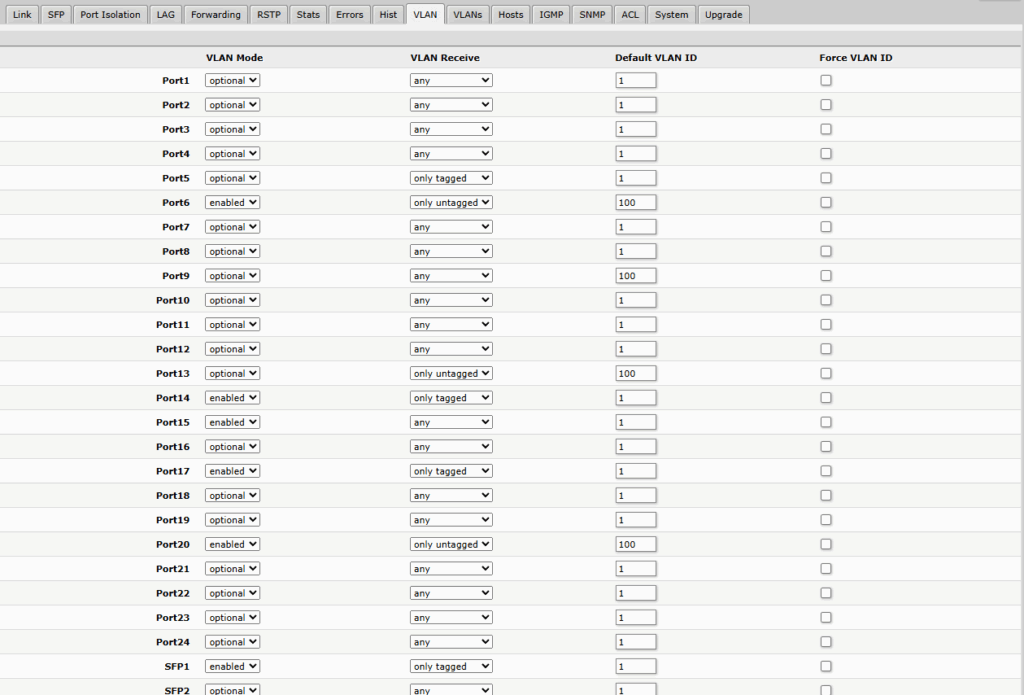
Mikrotik Switch configurations – only web gui view.
This setup which will allow adding new machines and communication between router and devices.
Mikrotik switch which It has low configuration options which are limited to write down the commands.


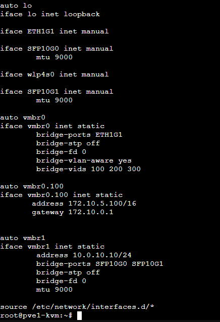
Proxmox Setup on Hypervisor level.
This is a view of the /etc/network/interfaces configuration file. I’ll explain how and why I use this setup with Proxmox. The configuration allows new virtual machines or containers to use different VLANs than the host, enabling network isolation at the VM level — managed by external devices rather than the host itself. The Proxmox host will be used solely for computing power and storage, while network management will be handled by MikroTik devices.

Summary
In this article, I walked you through the process of building a VLAN-aware Proxmox setup using MikroTik as the core network device. We covered:
- How to segment your network using VLANs
- Creating and assigning bridges on MikroTik
- Assigning IP addresses and setting up DHCP for each VLAN
- Configuring firewall and NAT rules to isolate traffic
- Enabling controlled forwarding between VLANs
- Using Proxmox as a compute/storage-only host while offloading network logic to MikroTik
This setup provides a scalable and secure foundation for any home lab or small enterprise environment.
Thank You
Thank you for taking the time to read this article!
I hope it helped you better understand how to combine MikroTik with Proxmox to build a flexible and secure virtualized network.
If you found it useful, feel free to share or follow for upcoming posts in the home lab how-to series